How a brushless drone motor works
A brushless motor turns because its speed controller (the ESC) switches current through three sets of copper coils in turn. Each switch makes the stator’s teeth into electromagnets that pull the permanent magnets in the spinning bell a little further round: an FPV motor with 12 teeth and 14 magnets needs 42 switches for one turn. There are no brushes. The switching is electronic, timed from the voltage the passing magnets induce in the coil that’s switched off.
What “brushless” means
An ordinary DC motor switches its own current: carbon brushes rub on a segmented ring (the commutator) on the spinning shaft, so the coils on the rotor swap polarity as it turns. The brushes spark, wear out and limit the speed. A brushless motor turns that inside out. The coils stay still on the stator, the magnets spin, and an electronic controller does the switching. Nothing rubs but the bearings, so an FPV motor can run at 30,000 rpm and more for hundreds of flights. Toy drones still use small brushed (“coreless”) motors because they need no ESC.
A real motor, taken apart
Every FPV motor is built the same way: a still stator wound with copper inside a spinning bell lined with magnets. Here is a real one, the iFlight XING2 2207, a typical 5-inch freestyle motor, taken apart along its axis: every part named, what it does and what it’s made of. The numbers are iFlight’s own for this motor; the inside parts it doesn’t publish are marked typical. Every part is drawn to the same scale; only the gaps between them are added.
- 2207 stator 22 × 7 mm
- 12N14P 12 teeth, 14 magnets
- 1855 KV
- 31.6 g
- 4 × M3 on 16 mm
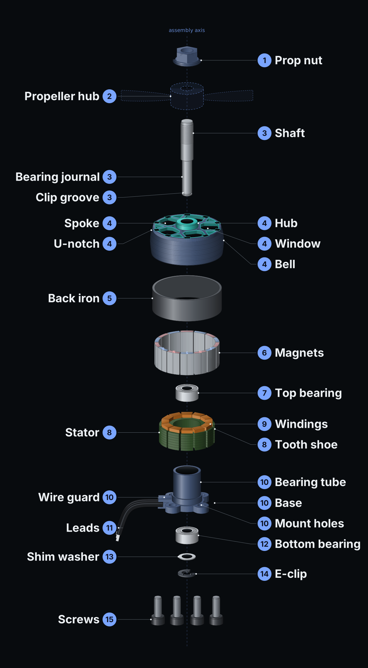
Diagram: every part, top to bottom
Prop nut
Clamps the propeller to the shaft. A serrated flange or a nylon insert keeps it from shaking loose.
XING2 2207: M5 flange nut, included
Propeller hub
Not part of the motor. The prop’s centre slides over the thread and sits on the bell’s hub; the nut squeezes it there, so the bell drives it.
5-inch props have a 5 mm bore
Shaft
Turns with the bell and carries the prop. It is pressed into the bell’s hub, runs in both bearings, and ends in a groove for the E-clip. A bent shaft makes the motor shake; it’s the part crashes ruin most.
XING2 2207: 5 mm titanium alloy with an M5 thread; sticks out 13.5 mm; 4 mm where it runs in the bearings
Bell (rotor)
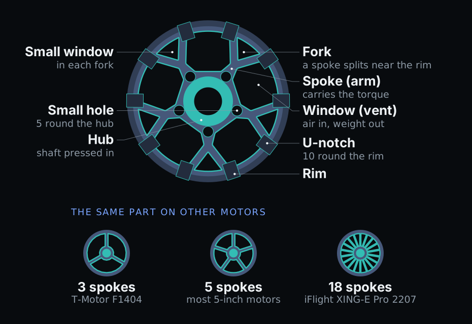
The spinning outer can. Its top is spokes and windows round a hub: the spokes carry the turning force from the magnets to the shaft, the windows let air through to the windings and save weight.
XING2 2207: one piece (a “unibell”) of 7075 aluminium, 29.08 mm across, body 19.1 mm tall; five spokes, each forked near the rim, and ten U-notches round the rim
Back iron (flux ring)
A steel ring pressed inside the bell. Aluminium doesn’t carry magnetism, so the magnets need steel behind them to close their magnetic circuit; without it they would lose most of their pull.
Steel, about 0.9 mm thick (typical; not published)
Magnets
Curved neodymium magnets glued inside the back iron, north and south in turn. 14 magnets make 7 north–south pairs: the “14P” in 12N14P. N52 is the strength grade; the H means it keeps its strength to about 120 °C.
XING2 2207: 14 N52H arc magnets, each with a slot down the middle to cut eddy-current heating
Top bearing
One of the two ball bearings the shaft spins in. Bearings are what wears out: a gritty feel or play in the bell means new bearings.
XING2 2207: NSK, 9 × 4 × 4 mm (outside × bore × width), one of two
Stator
The part that stays still inside the bell: a stack of thin steel sheets with 12 teeth, coated so the wire can’t short to it. Thin sheets, insulated from each other, stop eddy currents from heating the steel as the field reverses. Each tooth ends in a wide shoe that spreads its pull across the air gap to the magnets.
22 mm across × 7 mm tall: the “2207”; 12 teeth: the “12N”; sheets typically 0.2 mm
Windings
Enamelled copper wire wound round each tooth: 12 coils in three phases (A, B and C), four coils each. More turns of thinner wire give a lower KV and more torque per amp; fewer turns of thicker wire a higher KV.
XING2 2207: single-strand copper, 50 mΩ resistance
Base
Bolts to the arm and doesn’t turn. Its tube carries the stator on the outside and both bearings inside; a guard keeps the leads off the edge where they leave.
XING2 2207: 4 × M3 holes on a 16 mm circle (the “16 × 16” pattern), 2.5 mm plate
Leads
The three phase wires to the ESC. Which wire goes where doesn’t matter: swapping any two reverses the direction, which can also be set in the ESC.
XING2 2207: 3 × 20 AWG silicone, 160 mm
Bottom bearing
The second bearing, at the bottom of the tube. With the top one it keeps the shaft straight.
XING2 2207: NSK, 9 × 4 × 4 mm
Shim washer
A thin washer between the bottom bearing and the clip that takes up end play, so the bell doesn’t knock up and down.
Typically 0.1–0.3 mm; not published
E-clip (circlip)
Snaps into the groove at the bottom of the shaft and holds the bell and shaft in the base against the prop’s pull. If it’s lost, the bell can come off in flight.
Spring steel
Mounting screws
Hold the base to the arm. Too long and they reach the windings and short the motor: use a length that leaves a millimetre or two of clearance.
XING2 2207: 4 × M3 × 8, included
How the parts fit together
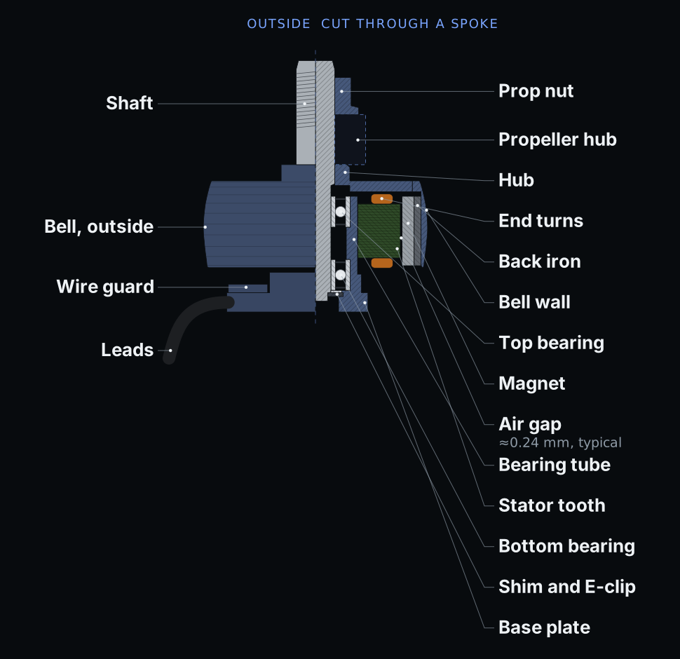
Cut in half along its axis, the motor shows what the exploded view can’t: the shaft runs in two bearings inside the base’s tube; the stator sits on the outside of that tube; and the bell turns round the stator with only a quarter of a millimetre of air between the magnets and the teeth. The smaller that air gap, the more of the magnets’ pull reaches the stator.
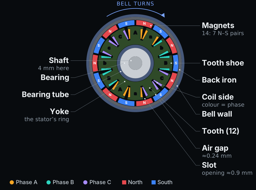
The windings and the magnets
Seen from above, cut across at mid-height. Twelve teeth carry the coils, coloured here by phase; capital and small letters are wound in opposite directions. The usual order for a 12-tooth, 14-magnet motor is AabBCcaABbcC. Each phase’s coils sit in pairs, so when current flows they make north and south poles side by side that line up with the magnets.
The bell’s top: spokes and windows
The “spokes” on top are its arms, and the openings between them are windows (vents). Makers shape them to their own taste: across the motors on this site the count runs from 3 to 24, straight, curved or forked like the XING2’s, and 5 is the most common. More metal in the spokes makes a stiffer bell that survives crashes; bigger windows run cooler and lighter.
How it turns
- The stator stays still; the bell with its magnets turns round it. That’s why FPV motors are called outrunners: the spinning part is outside. An inrunner spins a magnet rotor inside a still case.
- The ESC sends current through two of the three leads at a time. The teeth on those phases become electromagnets and pull the nearest magnets round.
- It moves the current on six times per electrical cycle. With 14 magnets (7 north–south pairs) that’s 7 cycles, or 42 switches, for every turn of the bell.
- There are no position sensors. The ESC watches the voltage the magnets induce in the lead it isn’t driving (back-EMF) to know when to switch next.
- Heat comes from the copper (current squared times the winding’s resistance) and from the steel, as its field reverses thousands of times a second. That’s why the windows, the thin sheets and the magnets’ temperature grade matter.
| Step | Current in | Current out | Off: the ESC listens |
|---|---|---|---|
| 1 | A | B | C |
| 2 | A | C | B |
| 3 | B | C | A |
| 4 | B | A | C |
| 5 | C | A | B |
| 6 | C | B | A |
A, B and C are the three leads. Each cycle moves the bell on by one pair of magnets, so with 7 pairs, 7 cycles make a turn. To see it, open the XING2 2207’s 3D model and press Magnetic field.
What the ESC does
- Six transistors per motor. Two MOSFETs on each lead connect it to the battery’s plus or minus, or to neither.
- Throttle is pulse-width modulation. The ESC switches the active pair on and off tens of thousands of times a second (24 to 96 kHz in firmware such as Bluejay). The share of “on” time sets the voltage the motor sees.
- Timing. It switches a few degrees before each magnet reaches its tooth, to make up for the time the coil’s current takes to build.
- Sensorless. FPV ESCs find the magnets from the back-EMF on the idle lead, so the motor needs no sensors. Cars and e-bikes often add Hall sensors, to start smoothly under load.
- Firmware. BLHeli_S and its open-source successor Bluejay run 8-bit ESCs; AM32 and BLHeli_32 run 32-bit ones. With bidirectional DShot the ESC sends each motor’s RPM back to the flight controller, which uses it to filter out motor noise.
Torque, KV and efficiency
- Torque grows with current, and the constant is the inverse of KV: torque per amp is about 9.55 ÷ KV newton-metres. The XING2’s 1855 KV gives about 5.1 mN·m per amp.
- So a higher-KV motor needs more current for the same torque, and suits a lower-voltage pack: for 5-inch quads, about 1,700 to 2,000 KV on 6S and 2,300 to 2,750 KV on 4S.
- Efficiency, measured as grams of thrust per watt, falls as the throttle rises, because the copper’s losses grow with the square of the current. On iFlight’s bench the XING2 makes 4.4 g/W at 50% throttle and 2.0 g/W at full throttle.
Outrunner vs inrunner
FPV motors are outrunners: the magnets sit outside, on a large radius, which gives more torque for the current, so they can swing a prop directly. An inrunner puts a small magnet rotor inside the coils. It’s compact and spins faster but has less torque, so it usually drives through a gearbox, as in RC cars, or spins a small ducted fan.
Reading a motor’s name
2207: the stator is 22 mm across and 07 mm tall. A wider or taller stator has more torque. Every size, compared.1855KV: with no prop it turns about 1,855 rpm per volt, so about 44,500 rpm on a 24 V (6S) pack. With a prop it turns much slower.12N14P: 12 stator teeth (N) and 14 magnet poles (P).
Teeth and magnets across our motors
- 12N14P: 307 motors, 13–36 mm stators
- 9N12P: 109 motors, 7–23 mm stators
- 9N14P: 1 motor, 14 mm stator
Wider stators take more teeth and magnets; the smallest whoop motors make do with 9 teeth and 12 magnets.
Where motors differ
- Bell top: 3 to 24 spokes, straight, curved or forked; one piece (“unibell”) or with a separate top.
- Shaft: 5 mm with an M5 thread on 5-inch motors and up; 1.5 or 1 mm on small ones. Titanium alloy (sometimes hollow, to save weight) or steel.
- Magnets: N52H on most; N52SH keeps its strength to about 150 °C.
- Windings: one thick strand or several thinner ones, more or fewer turns.
Mounting patterns
- 4 × M3 on 16 mm (“16 × 16”): 22–25 mm stators, 5-inch. 2207 motors, 2306 motors.
- 4 × M3 on 19 mm: 28 mm stators and up, 7-inch and bigger.
- 4 × M2 on 12 mm: 14–20 mm stators, 3- to 4-inch.
- 4 × M2 on 9 mm: 11–14 mm stators, 2- to 3-inch.
- 3 × M1.4 on 6.6 mm: 7–11 mm stators, tiny whoops.
What wears and what breaks
- Bearings wear: grit, noise or play means replacing both.
- Shafts bend in crashes; most makers sell spares.
- Magnets can chip or come unglued after a hard hit: look through the windows.
- Windings short if a screw is too long or the coating gets scraped.
- A lost E-clip lets the bell come off.
Sources
Drawn by Drone Motors from the iFlight XING2 2207’s published numbers, dimension drawing and product renders. Our drawing, not iFlight’s: no logos or markings. The stator’s teeth, the magnets’ thickness, the air gap, the back iron and the shim are typical for a 2207 and not published.
- iFlight: XING2 2207 4S 6S FPV Motor (product page)
- iFlight: XING2 2207 1855KV test report (spec table, dimension drawing, thrust data)
- iFlight: XING2 2207 2755KV test report
- iFlight: XING2 2207 product renders (teal 1855KV and black 1750KV galleries), used for shape and finish


The iFlight XING2 2207, its specs and thrust · All motors · Every size